Transforming Views and Layers
Recommended read first:
In The Foundational Building Blocks of iOS UI, we talked about views and layers, the foundational building blocks of UIKit and Core Animation, respectively, and learned how to build hierarchies of each and arrange them using their sizes and positions. But there’s one more key building block we need to explore when it comes to establishing where a view/layer is drawn in the hierarchy: transforms.
Applying a transform to a view allows you to change where its contents are drawn without affecting its underlying size or position. This is mainly used for temporary changes to a view, which is especially useful around things like animations.
The most common types of transforms you’ll use are scales, rotations, and translations.
![]()
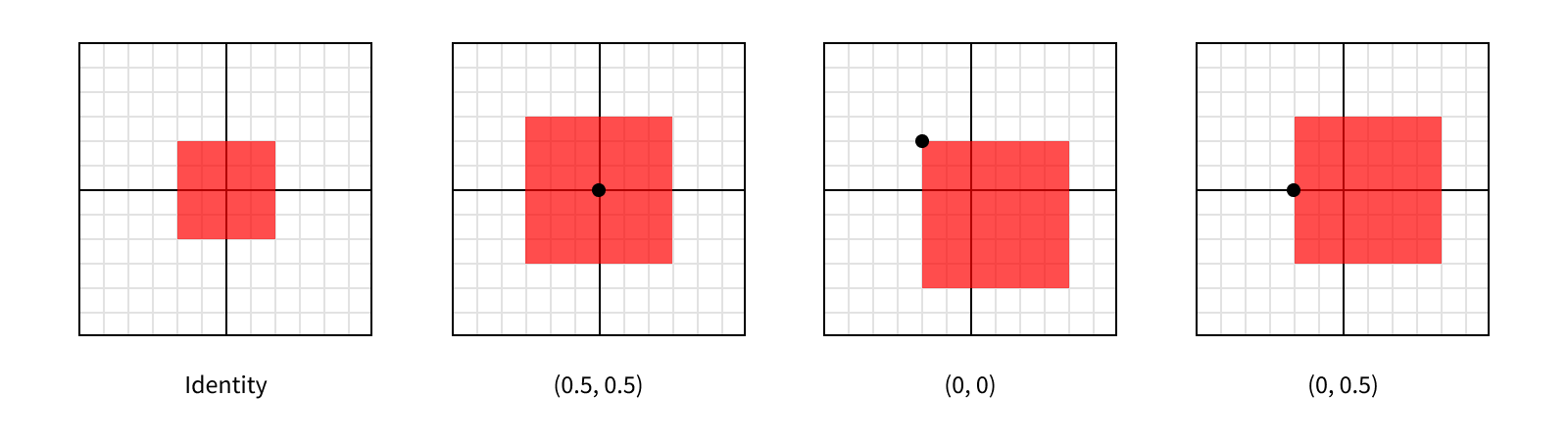
On the far left, we have the identity transform. Applying the identity transform to a view will result in its size and position staying exactly the same. In fact, all views have a transform, controlled by their transform property - but it defaults to .identity, so visually they’re “untransformed”.
The next view has a scale transform applied to it. This affects the visual size of the view. In this example, we’ve applied a scale of 2 on the X axis and 2.5 on the Y axis.
view.transform = CGAffineTransform(scaleX: 2, y: 2.5)
Here’s where we can start to the effect of using transforms. Visually, the view is over twice as large as before, but its bounds.size hasn’t changed.
The third view has a rotation applied to it. As the name suggests, this rotates the view. In this example, we’ve applied a rotation of 45º. The layout system thinks about angles in terms of radians though, rather than degrees, so we actually need to provide a value of π/4.
view.transform = CGAffineTransform(rotationAngle: CGFloat.pi / 4)
The final view has a translation applied to it. This simply repositions the view.
view.transform = CGAffineTransform(translationX: 100, y: 50)
While each of these is applicable to certain use cases on its own, the real power of transforms comes from their ability to be combined. You’ll often see these types of transforms applied on top of each other to create more complex transforms.
view.transform = CGAffineTransform.identity         // Start with the identity (no transform).
                    .translatedBy(x: 100, y: 50)    // Then translate it.
                    .rotated(by: CGFloat.pi / 4)    // Then rotate it by 45º.
                    .scaledBy(x: 2, y: 2.5)         // Then scale it up.
One important thing to remember while combining transforms is the order the transforms are applied in matters. Each transform is represented by a matrix, and under the hood combining transforms simply means multiplying the matrices. If you’ve taken a linear algebra course, you may remember matrix multiplication is not commutative. In order words, multiplying matrix A times matrix B is not the same as multiplying matrix B times matrix A.
There is a standard order in which to combine transforms to get the “expected” results - what we tend to think about as applying each transform separately. You might hear these referred to as TRS transforms, referring to the order in which they are applied: (1) translate, (2) rotate, and (3) scale. That said, you can apply transforms in any order you wish, creating different effects with each ordering.
![]()
Working with Frames
Transforms change where the view is drawn in its superview’s coordinate space, with no effect on its own coordinate space. In the last post we learned the frame property reflects where a view is in its parent’s coordinate space. So what happens to a view’s frame when there’s a transform applied? Apple’s documentation for the frame property calls out this situation specifically with a big warning:
If the transform property is not the identity transform, the value of this property is undefined and therefore should be ignored.
Put simply: If you’re dealing with a view that might have a transform applied to it, don’t rely on its frame. It’s safer to use a combination of the view’s bounds, position, and anchorPoint instead1.
In practice, the view’s frame will be a bounding box around where it appears on screen. Let’s take another look at some different transforms we can apply to a view with the resulting frames shown as a black outline around the view.
![]()
In most cases the frame still reflects an outline of the view, but when we apply the rotation it becomes clear it’s acting as a bounding box. However, since this is undocumented behavior (and the property is documented as being undefined in this case), it’s best to avoid using the frame for sizing or positioning altogether when transforms may be involved. That said, checking the frame can still be really useful for debugging purposes and it shows up in the standard debug description for views, so it’s important to understand what it represents.
Note rotations aren’t the only type of transform that can cause the frame to diverge from the displayed rect, it’s just the only of these simple three categories. That’s right - there’s more to transforms than scaling, rotating, and translating! The rendering system can handle a wide variety of transforms, but to unlock the full potential of transforms we need to explore beyond UIView’s transform property.
Transforming Layers
Layer’s also have a transform property, but it’s represented using a different type than its view counterpart. While views use a CGAffineTransform, layers use a CATransform3D. So what’s the difference?
Affine transforms work in a 2-dimensional world. Notice the translation and scaling methods take an X and a Y value. As the name suggests, a CATransform3D can represent a 3-dimensional transformation, adding in the Z axis. This makes 3D transforms much more powerful than affine transforms. Just like how all squares are rectangles, but not all rectangles are squares, you can represent any affine transform as an equivalent 3D transform, but not all 3D transforms can be represented by an affine transform.
All transforms actually happen at the layer level. Applying a new transform to your view will pass the new value through to the layer and vice versa. The fact that not all layer transforms can be represented by an affine transform makes this relationship a bit more complicated though, since reading a view’s transform property when its layer has a non-affine-representable transform applied to it will return an undefined value.
Views have a second property, transform3D, that directly correlates to the view’s layer’s transform without converting it to an affine transform. It’s safer, if slightly less convenient, to use this variant of transforms when you’re not sure what transform might have been applied to a view.
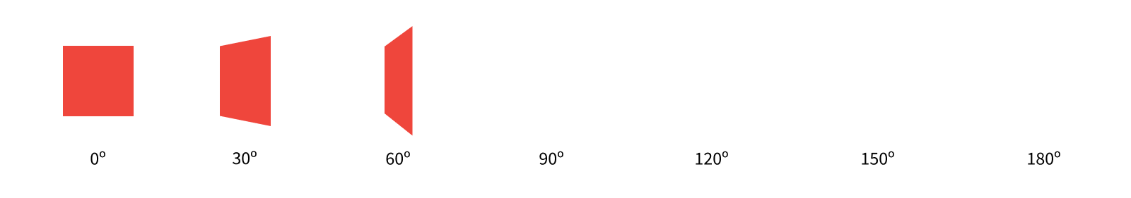
In the first post in this series, we talked about a layer’s anchorPoint controlling how its position was interpreted, and how it was easiest to leave it at (0.5, 0.5) most of the time. Well, transforms are the main reason you might want to change that value. This is because transforms are applied relative to the layer’s anchor point. For example, if we apply a scale transform to a layer, it will be scaled away from (or towards) its anchor point.
Each of these layers are scaled by the same amount (by a factor of 1.5 on each axis), so they all end up being the same size after the transformation. But since they each have a different anchor point, they were scaled relative to a different point within the layer, giving them different appearances.
It’s important to keep in mind each of these layers still has the same position and bounds. We haven’t changed the layer’s size in its own coordinate space, we’ve simply changed how it’s rendered within its parent’s coordinate space.
Just like with views, we can check our layer’s effective size and position in its parent’s coordinate space by looking at its frame. But like with views this frame isn’t reliable when certain transformations are involved.
Since all sublayers are arranged within their superlayer’s coordinate space, applying a transform to a layer will affect all of the layers in the hierarchy beneath it. This is useful behavior, since it makes it easy to transform a section of your hierarchy without knowing what all is in that hierarchy, only what the top layer is. You can even apply different transforms at different levels of the hierarchy2, which will build on top of each other.
It’s a 3D World
As demonstrated by the fact we can perform 3-dimensional transforms, layers live in a 3-dimensional world. But the size of a layer’s bounds only specifies 2 dimensions, a width and a height, and its position and anchorPoint only specify the location of those points on two axes, X and Y. What gives?
Most of the time, you’ll work with layers in 2 dimensions. After all, there’s no real depth to the screens on our devices, so any visual depth isn’t “real,” and we can already specify which layers are “closer” to the screen by changing the order of sublayers. Having the bounds and position work in two dimensions lets us think about arranging layers in a much simpler model.
When you do need to position a layer along the Z axis, you can augment its position by giving it a zPosition. This is mainly useful for 3D transformations, but changing a layer’s zPosition can also affect the visual ordering of sublayers, even if each layer individually appears the same. It’s best to stick to reordering sublayers when you’re simply trying to move one in front of the other, but controlling the position on the Z axis can be a useful technique in more complex transitions.
Wait a minute - did we just say an individual layer will visually appear the same even if we change its zPosition? Shouldn’t it appear closer or further away? Well, turns out this isn’t quite how it works. The rendering system doesn’t have any perspective built in (otherwise known as orthographic projection). This means regardless of the “distance” an object is to the screen, it will be drawn at exactly the same size. So moving our layers along the Z axis doesn’t affect them in any noticeable way on its own.
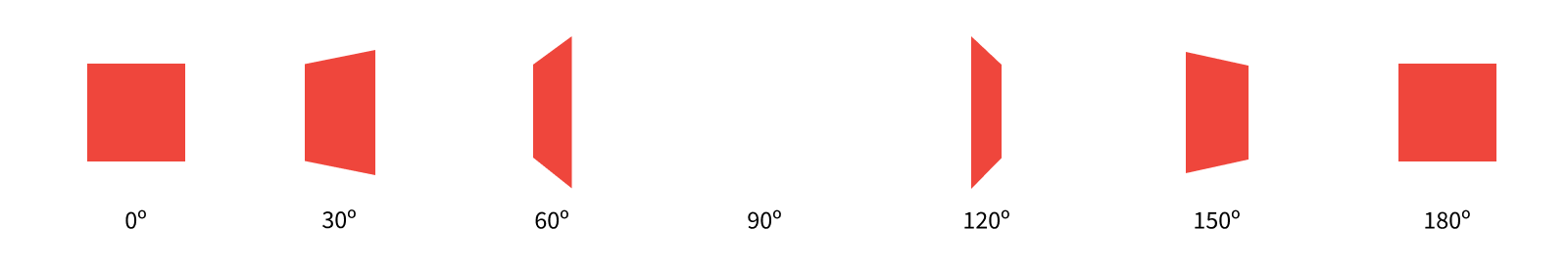
Taking this a step further, orthographic projection also means as we rotate a layer around its X or Y axis, so part of the layer is getting closer to us and part is getting further away, this “distance” change isn’t apparent, but rather the layer appears to be shrinking along the orthogonal axis. Let’s see what this looks like as we rotate a layer along its Y axis.
The CATransform3DRotate method takes a transform and returns a new transform with the specified rotation applied. The first parameter to the method is the initial transform. The second is the angle to rotate in radians, where positive values indicate a clockwise rotation. The last three parameters define the x, y, and z components of the vector around which to rotate.
If this sounds a lot more complicated than the affine rotations we discussed before… well, it is. This illustrates well one of the key trade-offs you often face between controlling visual characteristics with views and layers: the higher the level of abstraction you use, the simpler your API, but the less control you have.
For our example, we want to rotate around the Y axis, so we’ll set x and z to 0 and y to 1. We’re rotating counterclockwise around the axis, so our rotation angle is negative3. Since our starting transform is the identity transform, we can either call the CATransform3DRotate function, or use the CATransform3DMakeRotation function which omits the starting point.
layer.transform = CATransform3DMakeRotatation(.pi / 3, 0, 1, 0)

We can add some perspective to the layer to make the rotation more apparent. We’ll do so by setting its transform’s m34 to give the transform some perspective. M34 refers to the entry in the third row and fourth column of the matrix. This can be used to add perspective to a transform by setting it to -1.0 divided by the distance from which the layer is viewed. The default value for m34 is 0, or in other words infinite distance from the layer. The smaller the distance (so the larger the value of m34), the greater the effect of the perspective you’ll get. It’s good to start with relatively small distances (say values of -1/1000 or -1/500) and work from there.
Let’s see what our rotation looks like now with some perspective.

Much better!
Just like how a layer’s position is augmented with its zPosition, its anchor point is augmented with its anchorPointZ. But unlike the values in the anchorPoint, which measure a relative position within its bounds using 0 for one edge and 1 for the other, the anchorPointZ is measured in points. This is because layers have no depth, so there’s no size to measure relative to on the Z axis. You can think about this as layers always having a size of 0 on the Z axis4.
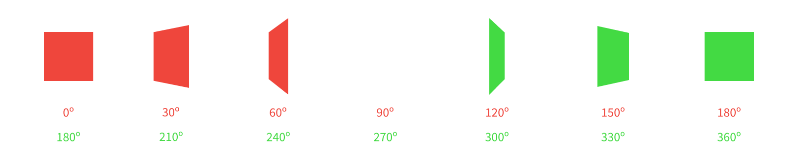
Since layers don’t have any depth, rotating them to a point where you can see their edge will never cause them to look like a box, but rather a sheet of paper (an infinitely thin sheet of paper). In fact, by default, they only have one face - meaning if you rotated the layer around to see it’s back (what’s normally facing away from the screen), it would all the sudden disappear!
Once the layer has rotated past 90º, the rendering system knows that we aren’t looking at the single face of the layer, so it doesn’t render anything where the layer should be. This behavior is configurable though. We can set the isDoubleSided property to tell the rendering system to always draw the layer’s contents, regardless of which side we’re looking at.
Now we can see the back side of our layer too. Here the back side looks the same, but keep in mind for more interesting content than solid red fill, we’d see the content drawn backwards, as if we were viewing a stained glass piece of art from the wrong side.
Note that even though our layer has two sides now, at 90º, where we’re looking directly at the layer’s edge, it still briefly disappears. This is due to the lack of depth in the layer. If we want to represent a solid object we can spin around, we need more advanced structures than a layer5.
A Practical Example
Having single-sided layers is more than just a performance optimization. We can use this characteristic of layers to our advantage in simplifying when we need to hide layers.
Let’s take an example of a layer we want to have two sides: imagine a flash card app, where you flip over the card to reveal more info on the opposite side. We can implement this as two layers, sized and positioned identically, with only their rotational offset different. The front side will start with the identity transform, while the back side will start with a 180º rotation around the Y axis. As we rotate the card, we’ll increase the rotation of both layers, keeping them offset by 180º.
And there we have it! Only one side of the card gets drawn at a time, and our two layers appear to be a single two-sided object.
-
In future posts we’ll explore some abstractions to make working with these properties much easy. ↩
-
Sometimes you want to apply a transform at a certain point in the hierarchy that applies to everything beneath a certain layer, but leave that layer alone. For these cases, you can set a
sublayerTransform, which applies only to a layer’s sublayers, but not to the layer itself. ↩ -
We could achieve an identical result by inverting our rotation axis to be (0, -1, 0) and providing a positive angle of rotation, giving us a clockwise rotation around the inverted Y axis. ↩
-
There’s an exception to every rule. A special layer subclass,
CATransformLayer, preserves the Z values of its sublayers during transforms. This is a rarely-used class and it behaves differently from other layers in a number of ways, so for the purposes of this discussion we’ll pretend it doesn’t exist. ↩ -
We’ll get there. But that’s way down the line, not the second post in this series. ↩